Slotted Waveguide Antennas
|
Slotted antenna arrays used with waveguides are a popular antenna in navigation, radar and other
high-frequency systems. They are simple to fabricate, have low-loss
(high antenna efficiency) and radiate
linear polarization with low
cross-polarization.
These antennas are often used in aircraft applications because they can be made to
conform to the surface on which they
are mounted. The slots are typically thin (less than 0.1 of a wavelength) and 0.5 wavelengths long
(at the center frequency of operation).
The slots on the waveguide will assumed to have a narrow width. Increasing the width increases the Bandwidth (recall that a fatter antenna often has an increased bandwidth); the expense of a larger width is a higher degree of cross-polarization. The Fractional Bandwidth for thin slots can be as low as 3-5%; wide slots can have a FBW on the order of 75%. An example of a slotted waveguide array is shown in Figure 1 (dimensions given by length a and width b)
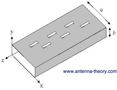 Figure 1. Basic geometry of a slotted waveguide antenna. As in the cavity-backed slot antenna, each slot could be independently fed with a voltage source across the slot. However, (especially for large arrays) this would be very difficult to construct, and I've never seen this done in practice. Instead, the waveguide is used as the transmission line to feed the elements. The position, shape and orientation of the slots will determine how (or if) they radiate. In addition, the shape of the waveguide and frequency of operation will play a major role. To understand what is going on, we'll need to understand the fields within the waveguide first. For a primer on waveguides, see here: waveguide primer. The dominant TE10 mode will be assumed to exist within the waveguide. Using the geometry of Figure 1, the fields that exist within the waveguide are given by:
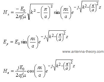
In the above, f is the frequency of interest, k is the
wavenumber and Magnetic fields tangent to a conductor produce electric currents on the surface. The resulting surface current density J [measured in Amps/meter] can be determined using the unit normal to the surface (n) as:
 On the top wall of the waveguide (where the slots are), the induced currents will be:
 Radiation occurs when the currents must "go around" the slots in order to continue on their desired direction. As an example, consider a narrow slot in the center of the waveguide, as shown in Figure 2.
 Figure 2. Waveguide with a thin slot centered about its width. In this case, the z-component of the current will not be disturbed, because the slot is thin and the z-current would not need to travel around the slot. Hence, the x-component of the current will be responsible for the radiation. However, at this location (x=a/2), the x-component of the current density is zero - i.e. no current and therefore no radiation. As a result, slots can not be placed in the center of the waveguide as shown in Figure 2. If the slots are displaced from the centerline as shown in Figure 1, the x-directed current will not be zero and will need to travel around the slot. Hence, radiation will occur. Note that the distance from the edge will determine the magnitude of the current. As a result, the power that the slot radiates can be altered by moving the slots closer or farther from the edge. In this manner, a phased array can be designed with varying excitation to each element. If the slot is oriented as shown in Figure 3, the slot will disturb the z-component of the current density. This slot will then radiate. If this slot is displaced away from the center line, the amount of power that it radiates can be adjusted.
 Figure 3. Horizontal slot in a waveguide.
If the slot is rotated at an angle about the centerline as shown in Figure 4, it will radiate. The power
it radiates will be a function of the angle (phi) that it is rotated - specifically given by
 Figure 4. Rotated slot antenna in a waveguide. In the next section, we'll examine slotted waveguides in more detail.
|
 is a constant that specifies how much power is added to the waveguide.
  . Note that the z-component of the current is still
responsible for radiation in this case. The x-component is disturbed; however the currents will have
opposite magnitudes on either side of the centerline and will thus tend to cancel out the radiation.
. Note that the z-component of the current is still
responsible for radiation in this case. The x-component is disturbed; however the currents will have
opposite magnitudes on either side of the centerline and will thus tend to cancel out the radiation.
Slotted Waveguide Antennas - Power Handling and Two-Dimensional Arrays