Radiation Pattern
|
A radiation pattern defines the variation of the power radiated by an antenna as a function of the direction away from the antenna. This power variation as a function of the arrival angle is observed in the antenna's far field.
As an example, consider the 3-dimensional radiation pattern in Figure 1, plotted in decibels (dB) .
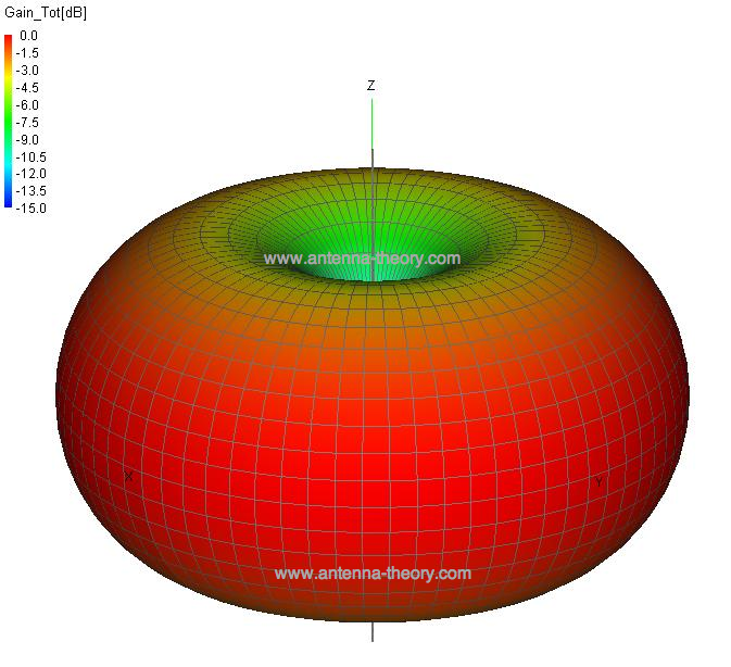 Figure 1. Example radiation pattern for an Antenna (generated with FEKO software).
This is an example of a donut shaped or toroidal radiation pattern. In this case, along the z-axis, which would correspond to the radiation directly overhead the antenna, there is very little power transmitted. In the x-y plane (perpendicular to the z-axis), the radiation is maximum. These plots are useful for visualizing which directions the antenna radiates.
Typically, because it is simpler, the radiation patterns are plotted in 2-d. In this case,
the patterns are given as "slices" through the 3d plane. The same pattern in Figure 1 is plotted
in Figure 2. Standard spherical coordinates are used, where
|
 is the angle measured off the z-axis, and
 is the angle measured counterclockwise off the x-axis.
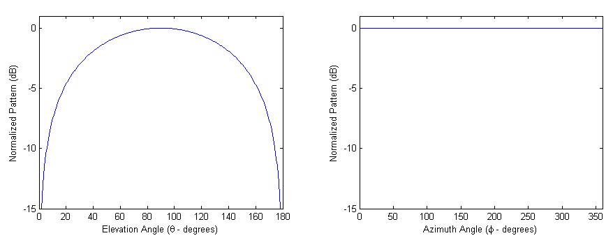
Figure 2. Two-dimensional Radiation Patterns.
|
If you're unfamiliar with radiation patterns or spherical coordinates, it may take a while to see that Figure 2 represents the same radiation pattern as shown in Figure 1. The radiation pattern on the left in Figure 2 is the elevation pattern, which represents the plot of the radiation pattern as a function of the angle measured off the z-axis (for a fixed azimuth angle). Observing Figure 1, we see that the radiation pattern is minimum at 0 and 180 degrees and becomes maximum broadside to the antenna (90 degrees off the z-axis). This corresponds to the plot on the left in Figure 2.
The radiation pattern on the right in Figure 2 is the azimuthal plot. It is a function of the azimuthal angle for a fixed polar angle (90 degrees off the z-axis in this case). Since the radiation pattern in Figure 1 is symmetrical around the z-axis, this plot appears as a constant in Figure 2.
A pattern is "isotropic" if the radiation pattern is the same in all directions. Antennas with isotropic radiation patterns don't exist in practice, but are sometimes discussed as a means of comparison with real antennas.
Some antennas may also be described as "omnidirectional", which for an actual antenna means that the radiation pattern is isotropic in a single plane (as in Figure 1 above for the x-y plane, or the radiation pattern on the right in Figure 2). Examples of omnidirectional antennas include the dipole antenna and the slot antenna.
The third category of antennas are "directional", which do not have a symmetry in the radiation pattern. These antennas typically have a single peak direction in the radiation pattern; this is the direction where the bulk of the radiated power travels. These antennas are very common; examples of antennas with highly directional radiation patterns include the dish antenna and the slotted waveguide antenna. An example of a highly directional radiation pattern (from a dish antenna) is shown in Figure 3:
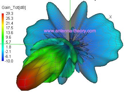 Figure 3. Directional Radiation Pattern for the Dish Antenna.
In summary, the radiation pattern is a plot which allows us to visualize where the antenna transmits or receives power.
Next Topic: Field Regions Antenna Basics Menu Antenna Theory - Home
|