Polarization - EM Waves and Antennas
Polarization of Plane Waves
Polarization (or Polarisation for our British friends) is one of the fundamental characteristics of any antenna. First we'll need to understand polarization of plane waves, then we'll walk through the main types of antenna polarization.
Linear Polarization
Let's start by understanding the polarization of a plane electromagnetic wave.
A plane electromagnetic (EM) wave is characterized by electric and magnetic fields traveling in a single direction (with no field variation in the two orthogonal directions). In this case, the electric field and the magnetic field are perpendicular to each other and to the direction the plane wave is propagating. As an example, consider the single frequency E-field given by equation (1), where the field is traveling in the +z-direction, the E-field is oriented in the +x-direction, and the magnetic field is in the +y-direction.
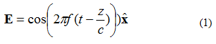
In equation (1), the symbol A plane wave is illustrated graphically in Figure 1.
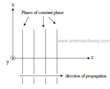 Figure 1. Graphical representation of E-field travelling in +z-direction. Polarization is the figure that the E-field traces out while propagating. As an example, consider the E-field observed at (x,y,z)=(0,0,0) as a function of time for the plane wave described by equation (1) above. The amplitude of this field is plotted in Figure 2 at several instances of time. The field is oscillating at frequency f.
|
 is a unit vector (a vector with a length of one), which says that
the E-field "points" in the x-direction.
is a unit vector (a vector with a length of one), which says that
the E-field "points" in the x-direction. 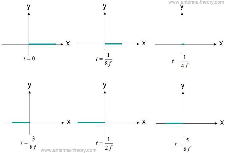
Figure 2. Observation of E-field at (x,y,z)=(0,0,0) at different times.
|
Observed at the origin, the E-field oscillates back and forth in magnitude, always directed along the x-axis. Because the E-field stays along a single line, this field would be said to be linearly polarized. In addition, if the x-axis was parallel to the ground, this field could also be described as "horizontally polarized" (or sometimes h-pole in the industry). If the field was oriented along the y-axis, this wave would be said to be "vertically polarized" (or v-pole).
A linearly polarized wave does not need to be along the horizontal or vertical axis. For instance, a wave with an E-field constrained to lie along the line shown in Figure 3 would also be linearly polarized.
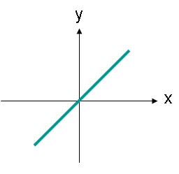 Figure 3. Locus of E-field amplitudes for a linearly polarized wave at an angle. The E-field in Figure 3 could be described by equation (2). The E-field now has an x- and y- component, equal in magnitude.
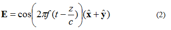 One thing to notice about equation (2) is that the x- and y-components of the E-field are in phase - they both have the same magnitude and vary at the same rate. Circular Polarization
Suppose now that the E-field of a plane wave was given by equation (3):
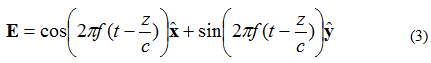 In this case, the x- and y- components are 90 degrees out of phase. If the field is observed at (x,y,z)=(0,0,0) again as before, the plot of the E-field versus time would appear as shown in Figure 4.
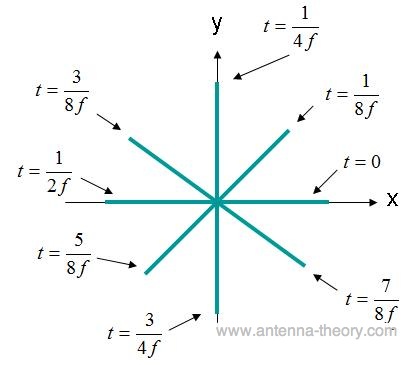 Figure 4. E-field strength at (x,y,z)=(0,0,0) for field of Eq. (3).
The E-field in Figure 4 rotates in a circle. This type of field is described as a circularly polarized wave. To have circular polarization, the following criteria must be met:
|
|
|
|---|
|
If the wave in Figure 4 is travelling out of the screen, the field is rotating in the counter-clockwise direction and is said to be Right Hand Circularly Polarized (RHCP). If the fields were rotating in the clockwise direction, the field would be Left Hand Circularly Polarized (LHCP).
Elliptical Polarization
If the E-field has two perpendicular components that are out of phase by 90 degrees but are not equal in magnitude, the field will end up Elliptically Polarized. Consider the plane wave travelling in the +z-direction, with E-field described by equation (4):
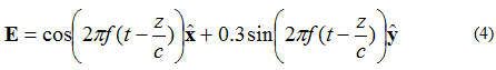 The locus of points that the tip of the E-field vector would assume is given in Figure 5.
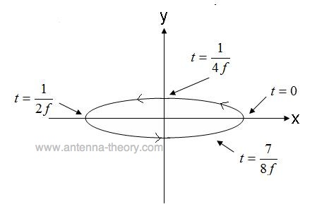 Figure 5. Tip of E-field for elliptical polarized wave of Eq. (4). The field in Figure 5, travels in the counter-clockwise direction, and if travelling out of the screen would be Right Hand Elliptically Polarized. If the E-field vector was rotating in the opposite direction, the field would be Left Hand Elliptically Polarized.
In addition, elliptical polarization can be defined by its axial ratio, which is the ratio of the major and minor axis amplitudes. For instance, the axial ratio of the wave given by equation (4) is 1/0.3 = 3.33. Elliptically polarized waves are further described by the direction of the major axis. The wave of equation (4) has a major axis given by the x-axis. Note that the major axis can be at any angle in the plane, it does not need to coincide with the x-, y-, or z-axis. Finally, note that circular polarization and linear polarization are both special cases of elliptical polarization. An elliptically polarized wave with an axial ratio of 1.0 is a circularly polarized wave; an elliptically polarized wave with an infinite axial ratio is a linearly polarized wave.
In the next section, we will use the knowledge of plane-wave polarization to characterize and understand antennas.
Polarization of AntennasNow that we are aware of the polarization of plane-wave EM fields, antenna polarization is straightforward to define.
The polarization of an antenna is the polarization of the radiated fields produced by an antenna, evaluated in the far field. Hence, antennas are often classified as "Linearly Polarized" or a "Right Hand Circularly Polarized Antenna".
This simple concept is important for antenna to antenna communication. First, a horizontally polarized antenna will not communicate with a vertically polarized antenna. Due to the reciprocity theorem, antennas transmit and receive in exactly the same manner. Hence, a vertically polarized antenna transmits and receives vertically polarized fields. Consequently, if a horizontally polarized antenna is trying to communicate with a vertically polarized antenna, there will be no reception.
In general, for two linearly polarized antennas that are rotated from each other by
an angle
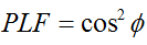
Hence, if both antennas have the same polarization, the angle between their radiated E-fields is zero and there is no power loss due to polarization mismatch. If one antenna is vertically polarized and the other is horizontally polarized, the angle is 90 degrees and no power will be transferred.
As a side note, this explains why moving the cell phone on your head to a different angle can sometimes increase reception. Cell phone antennas are often linearly polarized, so rotating the phone can often match the polarization of the phone and thus increase reception.
Circular polarization is a desirable characteristic for many antennas. Two antennas that are both circularly polarized do not suffer signal loss due to polarization mismatch. Another advantage of circular polarization is that a RHCP wave will reflect off a surface and be LHCP. This is advantageous because an antenna designed to receive RHCP waves will have some immunity to the signal-fading effects of reflected waves interfering with the desired wave. These are some of the reasons GPS signals from satellites are RHCP. Suppose now that a linearly polarized antenna is trying to receive a circularly polarized wave. Equivalently, suppose a circularly polarized antenna is trying to receive a linearly polarized wave. What is the resulting Polarization Loss Factor?
Recall that circular polarization is really two orthongal linear polarized waves 90 degrees out of phase. Hence, a linearly polarized (LP) antenna will simply pick up the in-phase component of the circularly polarized (CP) wave. As a result, the LP antenna will have a polarization mismatch loss of 0.5 (-3dB), no matter what the angle the LP antenna is rotated to. Therefore:
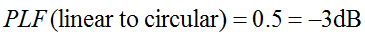
The Polarization Loss Factor is sometimes referred to as polarization efficiency, antenna mismatch factor, or antenna receiving factor. All of these names refer to the same concept.
Next Topic: Effective Aperture Antennas (Homepage)
This page on polarization and antennas is copyrighted. No portion can be reproduced without permission from the author. Copyright antenna-theory.com, 2009-2015. Polarization, antenna polarization, polarization of antennas.
|
 , the power loss due to this polarization mismatch will be described
by the Polarization Loss Factor (PLF):
, the power loss due to this polarization mismatch will be described
by the Polarization Loss Factor (PLF):