Antenna Impedance
Antenna impedance relates the voltage to the current at
the input to the antenna. This is extremely important as we will see.
Let's say an antenna has an impedance of 50 ohms. This means that if a sinusoidal voltage is
applied at the antenna terminals with an amplitude of 1 Volt, then the current will have an amplitude
of 1/50 = 0.02 Amps. Since the impedance is a real number, the voltage is in-phase with the
current.
Alternatively, suppose the impedance is given by a complex number, say Z=50 + j*50 ohms.
Note that "j" is the square root of -1. Imaginary numbers are there to give phase information. If the
impedance is entirely real [Z=50 + j*0], then the voltage and current are exactly in time-phase. If the
impedance is entirely imaginary [Z=0 + j*50], then the voltage leads the current by 90 degrees in phase.
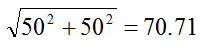
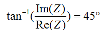
If Z=50 + j*50, then the
impedance has a magnitude equal to:
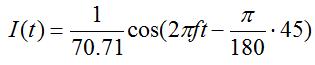
This means the phase of the current will lag the voltage by 45 degrees.
That is, the current waveform is delayed relative to the voltage waveform.
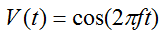
To spell it out, if
the voltage (with frequency f) at the antenna terminals is given by
Hence, antenna impedance is a simple concept.
Impedance relates the voltage and current at the input to the
antenna. The real part of the antenna impedance represents power that is
either radiated away or absorbed within the antenna. The imaginary part of the impedance
represents power that is stored in the near field of the antenna. This is non-radiated power.
An antenna with a real input impedance (zero imaginary part) is said to be resonant.
Note that the impedance of an antenna will vary with frequency.
While simple, we will now explain why this is important, considering both the low
frequency and high frequency cases.
Low Frequency
When we are dealing with low frequencies, the transmission line that connects the
transmitter or receiver to the antenna is short. Short in antenna theory always
means "relative to a wavelength". Hence, 5 meters could be short or very long, depending
on what frequency we are operating at. At 60 Hz, the wavelength is about 3100 miles, so
the transmission line can almost always be neglected. However, at 2 GHz, the wavelength
is 15 cm, so the little length of line within your cell phone can often be considered
a 'long line'. Basically, if the line length is less than a tenth of a wavelength, it
is reasonably considered a short line.
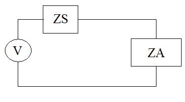
Consider an antenna (which is represented as an impedance given by ZA) hooked
up to a voltage source (of magnitude V) with source impedance given by ZS.
The equivalent circuit of this is shown in Figure 1.
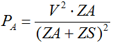
From circuit
theory, we know that P=I*V.
The power that is delivered to the antenna is:
If ZA is much smaller in magnitude than ZS, then no power will be delivered
to the antenna and it won't transmit or receive energy.
If ZA is much larger in magnitude than ZS, then no power will be delivered as well.
For maximum power to be transferred from the generator to the antenna, the
ideal value for the antenna impedance is given by:
The * in the above equation represents complex conjugate. So if ZS=30+j*30 ohms, then
for maximum power transfer the antenna should impedance ZA=30-j*30 ohms. Typically, the
source impedance is real (imaginary part equals zero), in which case maximum power
transfer occurs when ZA=ZS.
Hence, we now know that for an antenna to work properly, its impedance must not be too large
or too small. It turns out that this is one of the fundamental design parameters for
an antenna, and it isn't always easy to design an antenna with the right impedance - particularly
over a wide frequency range.
High Frequency
This section will be a little more advanced. In low-frequency circuit theory, the
wires that connect things don't matter. Once the wires become a significant fraction of
a wavelength, they make things very different. For instance, a short circuit has an
impedance of zero ohms. However, if the impedance is measured at the end of a
quarter wavelength transmission line, the impedance appears to be infinite, even though
there is a dc conduction path.
In general, the transmission line will transform the impedance of an antenna, making it
very difficult to deliver power, unless the antenna is matched to the transmission line.
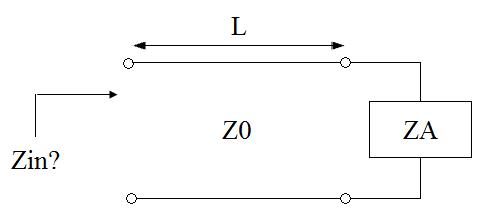
Consider the situation shown in Figure 2.
The impedance is to be measured at the end of a transmission line (with characteristic
impedance Z0) and Length L. The end of the transmission line is hooked to an antenna
with impedance ZA.
Figure 2. High Frequency Example.
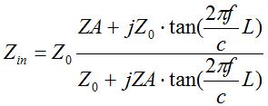
It turns out (after studying transmission line theory for a while), that the input
impedance Zin is given by:
This is a little formidable for an equation to understand at a glance. However, the
happy thing is:
If the antenna is matched to the transmission line (ZA=ZO), then the input impedance
does not depend on the length of the transmission line.
This makes things much simpler. If the antenna is not matched, the input impedance will
vary widely with the length of the transmission line. And if the input impedance isn't
well matched to the source impedance, not very much power will be delivered to the
antenna. This power ends up being reflected back to the generator, which can be a
problem in itself (especially if high power is transmitted). This loss of power
is known as impedance mismatch. Hence, we see that
having a tuned impedance for an antenna is extremely important. For more information
on transmission lines, see the
transmission line tutorial.
We see that an antenna's impedance is important for minimizing impedance-mismatch loss. A poorly matched
antenna will not radiate power. This can be somewhat alleviated via
impedance matching,
although this doesn't always work over a sufficient bandwidth (bandwidth is the next topic).
A common measure of how well matched the antenna is to the transmission line or receiver is known
as the Voltage Standing Wave Ratio (VSWR). VSWR is a real number that is always greater than or equal
to 1. A VSWR of 1 indicates no mismatch loss (the antenna is perfectly matched to the tx line). Higher
values of VSWR indicate more mismatch loss.
As an example of common VSWR values, a VSWR of 3.0 indicates about 75% of the power is delivered to
the antenna (1.25 dB of mismatch loss); a VSWR of 7.0 indicates 44% of the power is delivered
to the antenna (3.6 dB of mismatch loss). A VSWR of 6 or more is pretty high and will generally
need to be improved.
The parameter VSWR sounds like an overly complicated concept; however, power reflected by
an antenna
on a transmission line interferes with the forward travelling power - and this creates a standing voltage wave -
which can be numerically evaluated by the quantity Voltage Standing Wave Ratio (VSWR).
For more information, see the page on
VSWR and VSWR Specifications.
In the next section on antenna basics, we'll look at the very important antenna parameter known as bandwidth.
Antenna Theory (Home)

VSWR
Next Topic: Bandwidth