Yagi-Uda Antenna Design
|
The design of a Yagi-Uda antenna is actually quite simple. Because Yagi antennas have been extensively analyzed
and experimentally tested, the process basically follows this outline:
As an example, consider the table published in "Yagi Antenna Design" by P Viezbicke from the National Bureau of Standards, 1968, given in Table I. Note that the "boom" is the long element that the directors, reflectors and feed elements are physically attached to, and dictates the length of the antenna.
|
d=0.0085 SR=0.2 | ) |
|---|
| 0.4 | 0.8 | 1.2 | 2.2 | 3.2 | 4.2 |
|---|
| R | 0.482 | 0.482 | 0.482 | 0.482 | 0.482 | 0.475 |
| D1 | 0.442 | 0.428 | 0.428 | 0.432 | 0.428 | 0.424 |
| D2 | 0.424 | 0.420 | 0.415 | 0.420 | 0.424 | |
| D3 | 0.428 | 0.420 | 0.407 | 0.407 | 0.420 | |
| D4 | 0.428 | 0.398 | 0.398 | 0.407 | ||
| D5 | 0.390 | 0.394 | 0.403 | |||
| D6 | 0.390 | 0.390 | 0.398 | |||
| D7 | 0.390 | 0.386 | 0.394 | |||
| D8 | 0.390 | 0.386 | 0.390 | |||
| D9 | 0.398 | 0.386 | 0.390 | |||
| D10 | 0.407 | 0.386 | 0.390 | |||
| D11 | 0.386 | 0.390 | ||||
| D12 | 0.386 | 0.390 | ||||
| D13 | 0.386 | 0.390 | ||||
| D14 | 0.386 | |||||
| D15 | 0.386 |
| Spacing between directors, (SD/) | 0.20 | 0.20 | 0.25 | 0.20 | 0.20 | 0.308 |
| Gain (dB) | 9.25 | 11.35 | 12.35 | 14.40 | 15.55 | 16.35 |
|
There's no real rocket science going on in the above table. I believe the authors of the above document
did experimental measurements until they found an optimized set of spacings and published it. The spacing
between the directors is uniform and given in the second-to-last row of the table. The diameter of the
elements is given by d=0.0085 . The above table gives a good starting point
to estimate the required length of the antenna (the boom length), and a set of lengths and spacings
that achieves the specified gain. In general, all the spacings, lengths, diameters (including the boom diameter)
are design variables and can be continuously optimized to alter performance.
There are thousands of tables that further give results, such as how the diameter of the boom affects
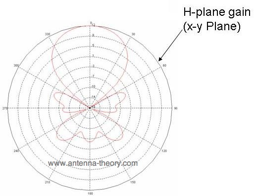
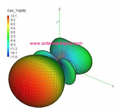
the results, and the optimal diameters of the elements. As an example of Yagi-antenna radiation patterns, a 6-element Yagi antenna (with elements spaced along the +x-axis and the individual elements oriented parallel to the z-axis) is simulated in FEKO (1 reflector, 1 driven half-wavelength dipole, 4 directors). The resulting antenna has a 12.1 dBi gain, and the plots are given in Figures 1-3.
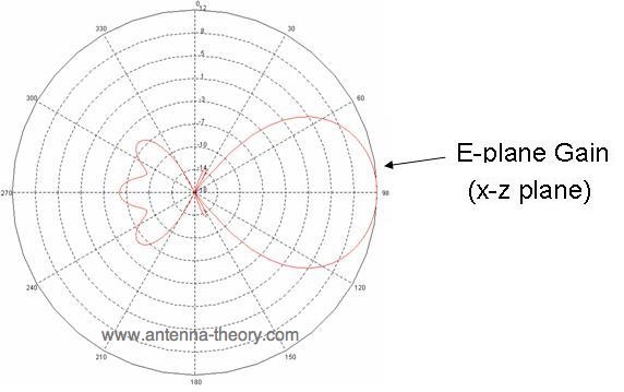
Figure 1. E-plane gain of Yagi antenna.
Figure 2. H-Plane gain of Yagi-Uda antenna.
Figure 3. 3-D Radiation Pattern of Yagi antenna.
Antennas (Home)
|