Cavity-Backed Slot Antennas
|
The previous page introducing slot antennas was primarily theoretical (giving you an intuitive idea of how slot antennas work); however, since it was about an infinite conducting plane it is not entirely practical. A practical slot antenna is the cavity-backed slot antenna. Unfortunately, the equations related to the cavity backed slot antenna are somewhat complicated and in my opinion don't give a good idea of how they work. Hence, I'll present the basics, present some experimental results and try to give an idea of design parameters. The basic cavity-backed slot antenna is shown in Figure 1 (in a rectangular cube of size A*B*C). The walls are metallic (electrically conducting), and the inside is hollow. On one end, a slot is cut out. The cavity is typically excited by a probe antenna in the intererior of the cavity, which typically is modelled as a monopole antenna. The exciting monopole antenna is shown in green.
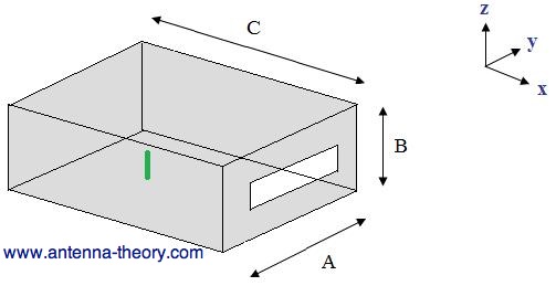 Figure 1. Cavity-backed slot antenna.
I'll give some experimental results for this antenna. Let the depth of the cavity C=91mm, the length be A=87mm and the height B=36mm. The height of the monopole antenna will be 29.5mm, so that the monopole is a quarter-wavelength long at 2.55 GHz. The monopole will be centered about the cavity in the y-direction, and 61.5mm behind the slot in the x-direction. The slot is 58mm long (in the y-direction) and 3 mm high (in the z-direction). The monopole is also 29.5mm (or a quarter wavelength) from the back edge of the cavity - this helps to make energy reflected from the rear wall return somewhat in-phase with the primary (forward directed) monopole radiation. S11 is measured for this antenna (relative to a 50 Ohm source), and is plotted versus frequency in Figure 2.
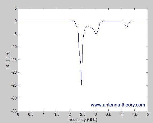 Figure 2. S11 as a function of Frequency for the Cavity-backed Slot Antenna. This cavity-backed slot antenna has a first resonance at about 2.45 GHz. At this frequency, the cavity backed slot antenna is roughly 0.474 wavelengths long - which is roughly the length of a resonant dipole antenna. S11 drops to below -20 dB at this frequency, indicating that most of the power is radiated away. The bandwidth, measured (somewhat arbitrarily) as the frequency span that S11 is less than -6 dB is roughly from 2.35 GHz to 2.55 GHz, giving a fractional bandwidth of slightly over 8%. Note that two other dips ('resonances') in the S11 curve occur, at approximately 3 GHz and 4.18 GHz. At these frequencies, the slot length is 0.58 and 0.81 wavelengths, respectively.
The volume of the cavity typically influences the bandwidth - a larger volume often yields a higher bandwidth. The material within the cavity (so far I have assumed it was filled with air), can be replaced with a dielectric medium. This reduces the resonant length of slot, allowing for a smaller antenna. The tradeoff is that the bandwidth and efficiency typically decrease with a dielectric cavity medium. The radiation pattern at 2.45 GHz is now presented. The H-plane (xy plane) is shown on the in Figure 3, and the E-plane (xz plane) is shown in Figure 4.
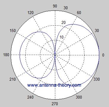
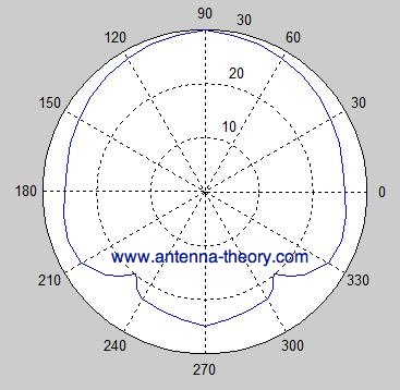
Figure 3. H-plane (xy plane). Angle measured off x-axis towards y-axis.
Figure 4. E-plane (xz plane). Angle measured off z-axis (to x-axis). The radiation pattern of the cavity backed slot antenna somewhat resembles that of a dipole antena in the forward H-plane. The 3-dB beamwidth is roughly 60 degrees in this plane. The radiation pattern is diminished in the rear H-plane, with a significant back lobe about 6 dB down from the peak of the main beam. In the E-plane, the pattern is fairly broad, with a 3-dB beamwidht of about 120 degrees. The broad pattern of these antennas make them well suited for use in antenna arrays. The peak gain of a thin slot is usually around 2-3 dB.
You may wonder how the antenna design parameters (A, B, C, monopole height and position) are determined. Typically the volume of the cavity is part of the space constraint given to an antenna designer. This means that someone may come to an antenna engineer and say "we have this volume available, can you obtain a 2.4 GHz antenna in here?" The height and position of the monopole, along with the slot length and height are then the design variables. From either computer simulation or experimental mockups a proper design can be chosen. Generally the antenna designer prefers increased volume for the cavity, and should determine the minimum overall volume for acceptable performance. Note that instead of a monopole feeding the cavity backed slot, the slot antenna could be directly fed (across the slot gap). In the next section, we'll look at slotted waveguides.
Previous: Intro to Slot Antennas Antenna Theory (Home)
|